Sensor Integration on Robotic Platform Paquitop
Designing and implementing a sensor integration system for enhanced obstacle detection on the Paquitop robotic platform.
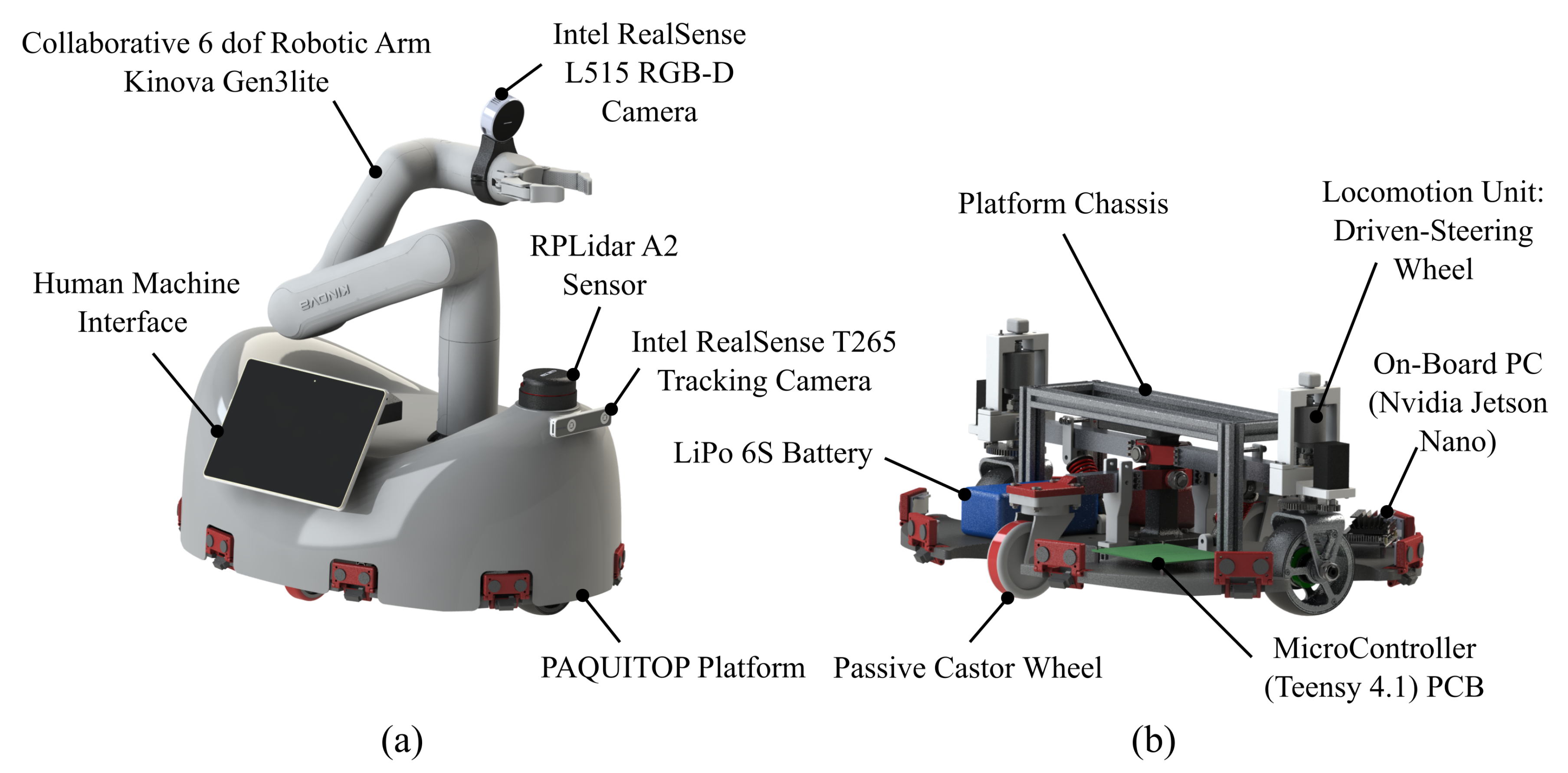
This project focuses on the development of a robust sensor integration system for the robotic platform Paquitop, as part of a curricular internship at the Interdepartmental Centre for Service Robotics (PIC4SeR) of Politecnico di Torino. The main objectives were to enhance obstacle detection capabilities and improve the safety and adaptability of the platform.
You can find the pdf version of the report for this project here.
Key contributions include the design and implementation of a distributed data acquisition system, PCB design for sensor boards, and integration of real-time communication using CAN bus.
Objectives
- Provide redundancy to the existing LIDAR system by adding ultrasonic and laser sensors for low-level obstacle detection.
- Enable detection of obstacles not visible to the LIDAR, such as descending steps or objects outside its 2D scanning plane.
- Design and deploy an autonomous data acquisition board using STM32 microcontrollers, ensuring real-time processing and minimal latency.

System Design
The proposed system incorporates 8 sensor groups, each consisting of:
- Ultrasonic sensors for planar distance measurement.
- Laser sensors to detect descending steps.
Limitations of Initial System Design
The initial system consisted on simple analog logic using comparators, enabling only for threshold detection. The new system design aimed to improve the detection capabilities and the adaptability of the system.
The initial system design relied heavily on analog components, leading to the following challenges:
- Latency issues due to I2C interrogation of multiple sensors to the I/O expander.
- Low signal stability caused by RC filter inaccuracies.
- No configurability of alarm thresholds.
- Complex wiring with numerous connections for each sensor group.
- Limited adaptability to new sensors or configurations.
Proposed Solution
Each sensor group has a microcontroller that communicates with the central controller via a CAN bus, enabling distributed data processing and system scalability. The microcontroller-based data acquisition boards convert analog signals to digital, ensuring precision while minimizing interference.
The revised system uses STM32 microcontrollers for each sensor group, leveraging their integrated ADC and CAN bus interfaces. Advantages include:
- Real-time configurability of alarm thresholds.
- Simplified wiring with a daisy-chain CAN bus topology.
- Flexibility to adapt to different sensors via software updates.

The project was developed through the following phases:
- Functional design and component selection.
- Schematic creation and PCB layout using KiCAD.
- Firmware development for both sensor boards and the central Teensy controller using STM32CubeIDE and Arduino IDE.
- Testing and debugging of the communication protocols and ADC performance.
PCB
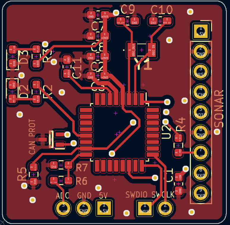
For the sensor modules a compact 27x27mm board has been designed housing an STM32G0B1KBT6 microcontroller, CAN transceivers, and power management circuits.


CAN Communication Protocol
The communication protocol has been designed as follows, enabling for remote configuration of the CAN_ID and the threshold values for each sensor group. It also allows for requesting distance measurements and sending alarms to the central controller.
| Name | ID | DLC | Data |
|---|---|---|---|
| SET_ID_CAN | 0x12 | 2 | 0: CMD | 1: CAN_ID |
| SET_THRESHOLD | 0x13 | 7 | 0: CMD | 1,2: Y_TH | 3,4: R_TH | 5,6: L_TH |
| DIST_REQUEST | 0x14 | 1 | 0: CMD |
| ALARM_YELLOW | 0x15 | 4 | 0: CMD | 1: CAN_ID | 2,3: DIST_SONAR |
| ALARM_RED | 0x16 | 4 | 0: CMD | 1: CAN_ID | 2,3: DIST_SONAR |
| ALARM_LASER | 0x17 | 2 | 0: CMD | 1: CAN_ID |
| DIST_ANS | 0x18 | 6 | 0: CMD | 1: CAN_ID | 2,3: LASER | 4,5: SONAR |